In modern CNC manufacturing, engineering diagrams and technical illustrations play a critical role in communicating complex machining concepts. These diagrams allow engineers, machinists, and designers to understand the relationships between the machine tool, workpiece, cutting tool, and workholding systems.
Technical diagrams are widely used in engineering manuals, manufacturing documentation, CNC training materials, and fixture design guides. They simplify complex machining processes and provide a visual representation of how machining systems function.
The most common diagrams used in machining documentation include:
- Fixture diagrams
- Machining diagrams
- Cutting tool diagrams
- 5-axis machining illustrations
Each of these diagrams represents a different aspect of the machining process and contributes to better understanding of manufacturing operations.
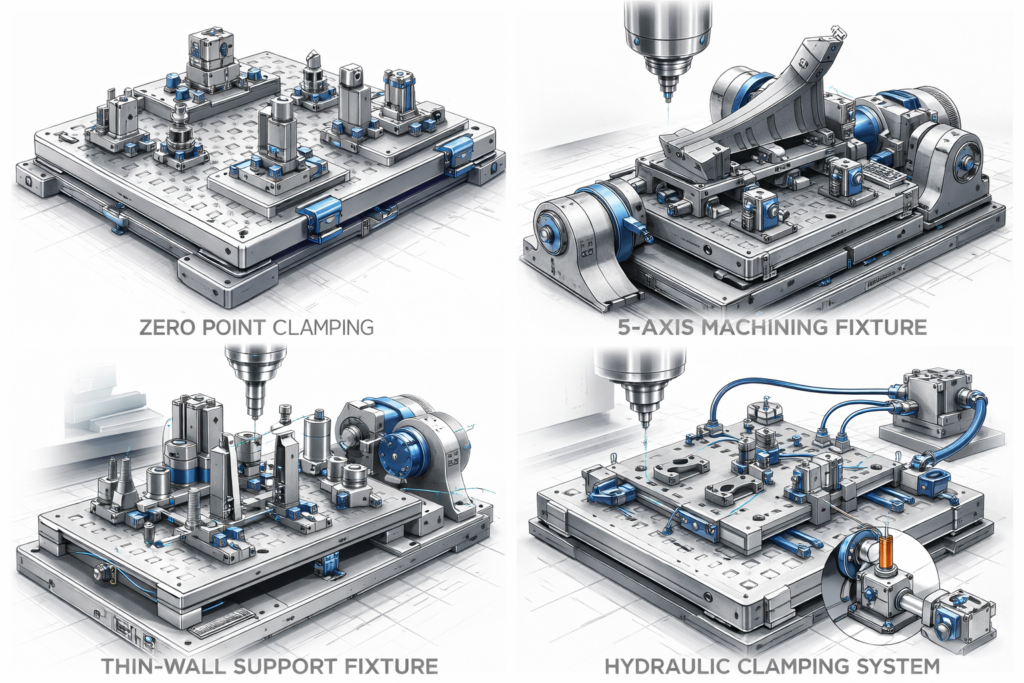
Fixture Diagram
A fixture diagram illustrates how a workpiece is positioned, located, and clamped during machining operations. Fixtures are essential for maintaining part stability and ensuring that machining operations are performed accurately.
Fixture diagrams typically show the relationship between the following components:
- fixture base plate
- locating pins or datum surfaces
- clamping elements
- workpiece geometry
- machine table interface
The primary purpose of a fixture diagram is to demonstrate how the workpiece is constrained in all six degrees of freedom. Engineers commonly use the 3-2-1 locating principle to achieve this constraint.
Key elements shown in fixture diagrams
Base Plate
The base plate connects the fixture to the CNC machine table and provides structural rigidity.
Locating System
Locating elements position the workpiece accurately before clamping occurs.
Clamping System
Clamps apply force to hold the workpiece securely during machining.
Support Structures
Support blocks or pads prevent deformation, particularly in thin or flexible components.
Fixture diagrams are essential during fixture design and manufacturing planning, allowing engineers to evaluate the mechanical stability of the workholding system.
Machining Diagram
A machining diagram illustrates the overall machining process, showing how the cutting tool interacts with the workpiece during material removal.
Machining diagrams typically include:
- the CNC spindle
- the cutting tool
- the workpiece
- the direction of tool movement
- feed and cutting directions
These diagrams help explain machining operations such as:
- milling
- drilling
- turning
- boring
Machining diagrams are especially useful in training environments because they clearly demonstrate how cutting forces, chip formation, and tool engagement occur during machining.
Information commonly shown in machining diagrams
Feed Direction
The direction in which the tool advances relative to the workpiece.
Cutting Direction
The direction of rotation of the cutting tool.
Depth of Cut
The vertical distance between the original surface and the machined surface.
Chip Flow
The direction in which chips are removed during machining.
Understanding machining diagrams helps engineers optimize cutting parameters, toolpaths, and machining strategies.
Cutting Tool Diagram
A cutting tool diagram illustrates the geometry of a cutting tool used in machining operations. Tool geometry plays a critical role in determining cutting efficiency, tool life, and surface quality.
Cutting tool diagrams typically display the following geometric features:
- rake angle
- clearance angle
- cutting edge
- tool nose radius
- flute geometry
These parameters influence how the tool interacts with the material during cutting.
Important geometric elements
Rake Angle
The rake angle controls chip flow and cutting efficiency. A positive rake angle reduces cutting forces, while a negative rake angle increases tool strength.
Clearance Angle
The clearance angle prevents the tool from rubbing against the machined surface.
Cutting Edge
The cutting edge is the part of the tool that removes material.
Flutes
Flutes provide space for chip evacuation during cutting.
Proper tool geometry selection is essential when machining difficult materials such as titanium alloys, hardened steels, and superalloys.
5-Axis Machining Illustration
A 5-axis machining illustration demonstrates how a cutting tool moves relative to the workpiece using multiple machine axes.
Unlike traditional 3-axis machining, where the tool moves only along X, Y, and Z directions, 5-axis machining introduces two additional rotary axes that allow the tool or workpiece to rotate.
These additional axes enable the machining of highly complex geometries.
Typical axis configuration:
| Axis | Function |
|---|---|
| X | Linear motion left-right |
| Y | Linear motion front-back |
| Z | Linear motion up-down |
| A | Rotation around X-axis |
| B | Rotation around Y-axis |
| C | Rotation around Z-axis |
5-axis machining illustrations usually show:
- the machine spindle
- rotary axes movement
- the workpiece orientation
- tool approach direction
These illustrations are particularly useful when explaining machining processes such as:
- turbine blade machining
- impeller manufacturing
- complex mold cavity machining
- aerospace structural parts
By allowing the tool to approach the workpiece from multiple directions, 5-axis machining significantly improves machining efficiency and surface quality.
Importance of Technical Diagrams in CNC Engineering
Engineering diagrams serve as powerful tools for communicating machining concepts and improving manufacturing processes.
They help engineers and machinists:
- visualize machining operations
- understand fixture design concepts
- analyze tool geometry
- plan machining strategies
In modern manufacturing environments, diagrams are often integrated into CAD/CAM systems, digital manufacturing simulations, and technical documentation.
Advanced workholding and machining solutions developed by companies such as Aspava Makina rely heavily on these types of engineering diagrams during the design and development of precision fixtures and clamping systems.
By combining clear technical illustrations with engineering analysis, manufacturers can improve machining accuracy, reduce setup time, and optimize production efficiency.