This technical guide explains 5-axis CNC kinematics, focusing on the differences between table kinematics and head kinematics, and how they affect CAM programming, vector logic, and plane definitions. The explanations follow the methodology commonly taught in Siemens 5-axis machining training material, which emphasizes orientation vectors, kinematic transformation, and safe multi-axis programming.
The goal is to make complex concepts such as tool-axis vectors, rotary axis solutions, tilted work planes, and TCP (Tool Center Point) easier to understand with visuals and structured explanations.
Understanding 5-Axis CNC Machine Architecture
4
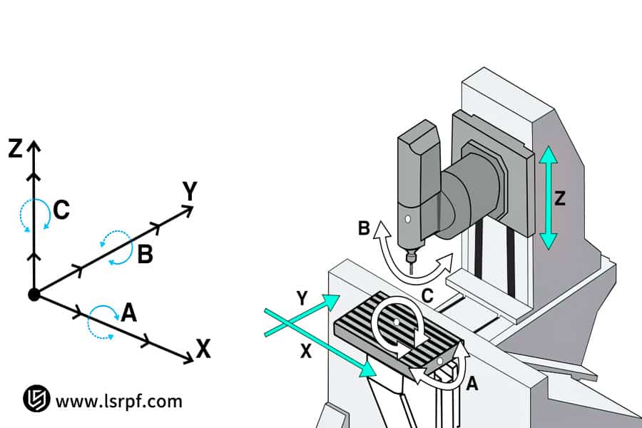
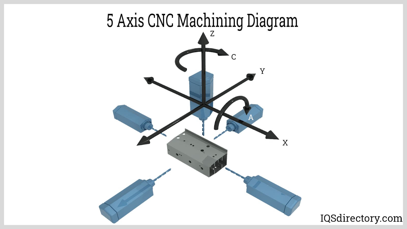
A 5-axis CNC machine adds two rotary axes to the traditional 3-axis system (X, Y, Z). These additional axes allow the tool or workpiece to rotate and orient in space.
Typical axis naming convention:
| Axis | Type | Description |
|---|---|---|
| X | Linear | Left / Right movement |
| Y | Linear | Forward / Back |
| Z | Linear | Up / Down |
| A | Rotary | Rotation around X |
| B | Rotary | Rotation around Y |
| C | Rotary | Rotation around Z |
With these axes, the tool can approach the part from almost any direction.
This allows machining of:
- Turbine blades
- Impellers
- Medical implants
- Aerospace parts
- Complex molds
According to Siemens training methodology, 5-axis machining operates using orientation vectors, not simply axis angles. The machine controller calculates the rotary movements required to achieve the desired orientation.
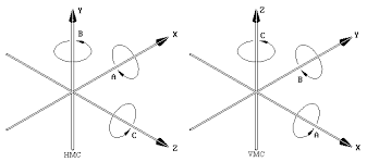
Machine Kinematics: Why It Matters
Kinematics describes how the rotary axes are physically arranged in the machine.
In practice, there are three main configurations:
| Kinematic Type | Description |
|---|---|
| Table-Table | Workpiece rotates |
| Head-Head | Tool head rotates |
| Head-Table | Mixed configuration |
The same CAM toolpath can produce completely different machine movements depending on the machine’s kinematic structure.
This is why post processors must match the machine configuration exactly.
Table Kinematics


4
In table kinematics, the rotary axes are located in the machine table.
The workpiece rotates, while the spindle mostly moves in X, Y, Z.
Common configurations:
- B + C rotary table
- A + C trunnion table
How it Works
The part is mounted on a rotating table.
When the machine needs a different tool orientation, the table rotates instead of the spindle head.
Advantages
- Very rigid spindle
- Good stability during heavy cutting
- Shorter tool length often possible
Disadvantages
- Heavy parts create inertia
- Large workpieces are harder to rotate
- Fixturing becomes critical
Table kinematics is very common in aerospace and mold machining.
Head Kinematics


ASPAVA 5 EKSEN TABLA KİNEMATİK
4
In head kinematics, the rotary axes are located in the spindle head.
Instead of rotating the workpiece, the tool itself tilts and rotates.
Typical designs
- Fork head
- Nutating head
- Swivel head
Advantages
- Large heavy parts remain stationary
- Better for large aerospace structures
- Workholding is simpler
Disadvantages
- Longer moment arm
- Reduced rigidity in extreme angles
- Tool holder collisions more likely
Head kinematics are common in large gantry machines and aerospace machining centers.
Mixed Kinematics (Head + Table)


4
Many machines use one rotary axis in the table and one in the head.
Example:
- B axis in spindle
- C axis in table
This hybrid structure provides:
- Good flexibility
- Reduced inertia
- Balanced machining performance
3+2 vs Simultaneous 5-Axis Machining
Siemens training materials divide 5-axis machining into two programming strategies.
3+2 Positioning
Also called:
- Positional 5-axis
- Indexed 5-axis
Process:
- Machine rotates to an angle
- Tool orientation stays fixed
- Cutting happens like 3-axis machining
Example operations:
- Angled holes
- Chamfers
- Side pockets
- Multi-face machining
Advantages:
- Easier programming
- Safer motion
- More predictable
Simultaneous 5-Axis
In this mode:
- All axes move continuously
- Tool orientation constantly changes
Applications include:
- Turbine blades
- Impellers
- Freeform surfaces
- Organic shapes
Simultaneous machining requires:
- CAM programming
- Accurate post processors
- Collision checking
- Smooth toolpaths
Vector Concept in 5-Axis CAM Programming
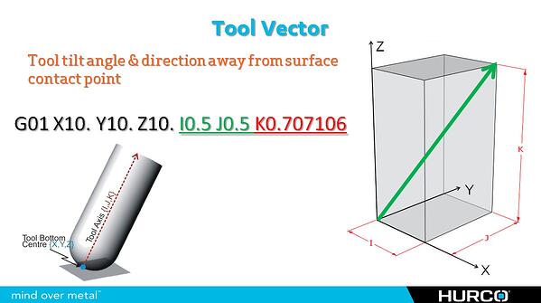

4
In CAM software, tool orientation is defined using vectors.
Instead of specifying machine angles, the software defines the direction of the tool axis in space.
A vector has three components:
V = (i, j, k)
Where:
| Component | Direction |
|---|---|
| i | X direction |
| j | Y direction |
| k | Z direction |
Example:
(0,0,1)
Means the tool points straight upward along Z.
The machine controller converts this vector into the required rotary axis angles.
Surface Normal and Tool Orientation
The surface normal vector is perpendicular to a surface.
Many toolpaths use the surface normal as the base orientation.
But the tool is usually tilted slightly using two angles:
| Angle | Purpose |
|---|---|
| Lead angle | Tilt forward |
| Lean angle | Tilt sideways |
Reasons for tilting the tool:
- Avoid cutting with tool center
- Improve chip evacuation
- Reduce tool wear
- Improve surface finish
CAM Plane Definitions
In multi-axis machining, defining the correct plane is essential.
There are several ways to define machining planes.
Plane by Normal Vector
Define the plane using a normal vector.
Common in modern CAM systems.
Plane by Two Vectors
Plane defined by:
- Primary direction
- Secondary direction
This fully defines orientation in 3D space.
Plane by Euler Angles
Using angles:
A
B
C
However, this approach can create ambiguity because multiple axis solutions may produce the same orientation.
Tilted Work Plane (Siemens Concept)
Siemens controllers commonly use tilted plane cycles such as:
CYCLE800
This rotates the coordinate system so the programmer can machine on an angled surface as if it were horizontal.
Example concept:
Original plane:
G17
After tilt:
G17 becomes the rotated machining plane
This simplifies programming dramatically.
Tool Center Point Control (TCP / TRAORI)
One of the most important features in 5-axis machining is Tool Center Point control.
In Siemens machines this is often called:
TRAORI
Purpose:
The machine keeps the tool tip exactly on the programmed path, even while the head rotates.
Without TCP:
- Tool length changes affect position
- Orientation shifts cause errors
With TCP:
- The tool tip remains constant
- Rotary axes automatically compensate
Safe 5-Axis Programming Strategy
A robust program usually follows this sequence.
1. Safe Start Position
Move to a safe location above the part.
2. Activate Tool and Compensation
Tool length and offsets applied.
3. Activate Orientation / Plane
Example:
CYCLE800
or tool vector.
4. Approach Move
Move near the surface safely.
5. Cutting Motion
Perform the machining operation.
6. Retract Move
Move away from the part safely.
7. Cancel Orientation
Return to standard plane.
Common Programming Mistakes
Even experienced programmers make errors in multi-axis machining.
Typical mistakes include:
Wrong Machine Kinematics
Post processor configured for the wrong machine type.
Reversed Tool Vector
Tool points into the part instead of away.
Rotary Axis Limits
CAM generates angles beyond machine capability.
Singularities
Axis combinations cause sudden rotations.
FAQ – 5 Axis Kinematics and Programming
What is the biggest difference between table and head kinematics?
Table kinematics rotates the workpiece, while head kinematics rotates the tool spindle.
Which kinematic structure is more rigid?
Table machines typically have more rigid spindles, but head machines are better for large heavy parts.
Why are vectors used instead of angles?
Vectors represent tool direction in space, allowing CAM systems to work independently of machine type.
What is a singularity in 5-axis machining?
A position where small orientation changes cause large rotary axis movements.
Why is TCP important?
TCP ensures the tool tip remains on the programmed path regardless of head movement.
Can all 5-axis machines run the same program?
No. The post processor must match the machine’s kinematic structure.
Conclusion
Understanding 5-axis machine kinematics is essential for safe and efficient machining.
The difference between table kinematics and head kinematics influences:
- CAM programming
- toolpath orientation
- collision risk
- workholding strategy
- machine dynamics
By mastering vectors, tilted planes, TCP control, and proper post-processing, programmers can fully exploit the power of 5-axis machining.
These principles—commonly taught in Siemens multi-axis training materials—form the foundation of modern high-precision manufacturing.